At the Tinaja Labs booth, called The Sense of Things, I had a full IoT system (Internet of Things) in place. Front to back I started with wireless sensors, to a Raspberry Pi that collected sensor data, to a Beaglebone Black running Node-Red (as a signal routing application), to newly introduced inexpensive wi-fi modules (the ESP8266), and finally to old-school X-10 light switches.
I’ve always described my setup as a home automation system that is built on a wireless sensor network. I first heard about the concept of the Internet of Things (IoT) in 2009. Home automation and wireless sensor networks are now included in the overarching concept of IoT and includes M2M (machine to machine) and industrial applications like manufacturing systems. IoT describes all the things that can be connected through internet technologies with sensors on one end, actuators on the other end and coordination software in the middle.
Overview of the IoT system
Download the OS image here. Read instructions here and learn about how to burn an OS image to a MicroSD card using WinDiskImager32. More info about setting up a MicroSD card here.
The system in place includes examples of typical components of an IoT system. On one end I had wireless sensors (based on XBee Series 1 radios), in the middle I had connecting and coordination system software (Node-Red), and on the other end I had charting and analysis (Graphite/Grafana) and actuation (wi-fi based LED control). Pretty much, that covers the basic areas of home automation.
Code for this setup is on Github at: TinajaLabs/makerfaire2015
Sensor PCB with XBee
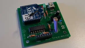
My MS-1; a Multi-Sensor PCB w XBee.
I designed this PCB a few years ago and it still works great. I deployed these in every room of our home. It has a 3.3V regulator, an XBee Radio, a temperature sensor (tmp36), a light sensor (CdS cell), and headers for 2 more sensors (mostly I’ve hooked up a hall effect sensor and an FSR, force sensitive sensor). I also included a rail to rail buffer chip to create a clean separation between the sensors. In hind-sight I probably didn’t need that.
The sensor board schematic and the PCB layout:

MS-1 PCB Layout
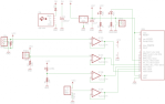
MS-1 Schematic
Using XCTU, a configuration tool (available for Windows, Mac, or Linux) from Digi, I configured the XBee Series 1 radio end points like this:
AP=2
CE=0
MY=
ID=1111 (same for all radios in your system)
CH=0C (same for all radios in your system)
Wi-fi Capacitive Touch Button
Download the OS image here. Read instructions here and learn about how to burn an OS image to a MicroSD card using WinDiskImager32. More info about setting up a MicroSD card here.
This is a new sensor setup, breadboarded, that uses a capacitive touch switch (Standalone Toggle Capacitive Touch Sensor Breakout – AT42QT1012) and an ESP8266 wi-fi PCB. The capacitive switch responds to touch and toggles a high/low voltage on the GPIO01 pin of the ESP8266. The ESP8266 is programmed to send the switch’s state over wi-fi to a web service on the Node-Red software. More about that in the Node-Red section below.
django-tagging 0.3.1 or greater
 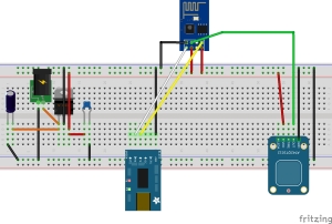
Here’s the Fritzing breadboard of the capacitive switch hooked up to an ESP8266. Find the code I used code on Github.
The Gateway “Stack”
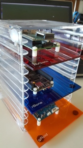
The picture below shows what I call my gateway rack (constructed from a CD caddy and CD sized pieces of colored Plexiglas from Tap Plastics). All of the functionality could probably be included on any one of these devices, but for the sake of experimentation and separation of functions, I set up 3 micro-computers:
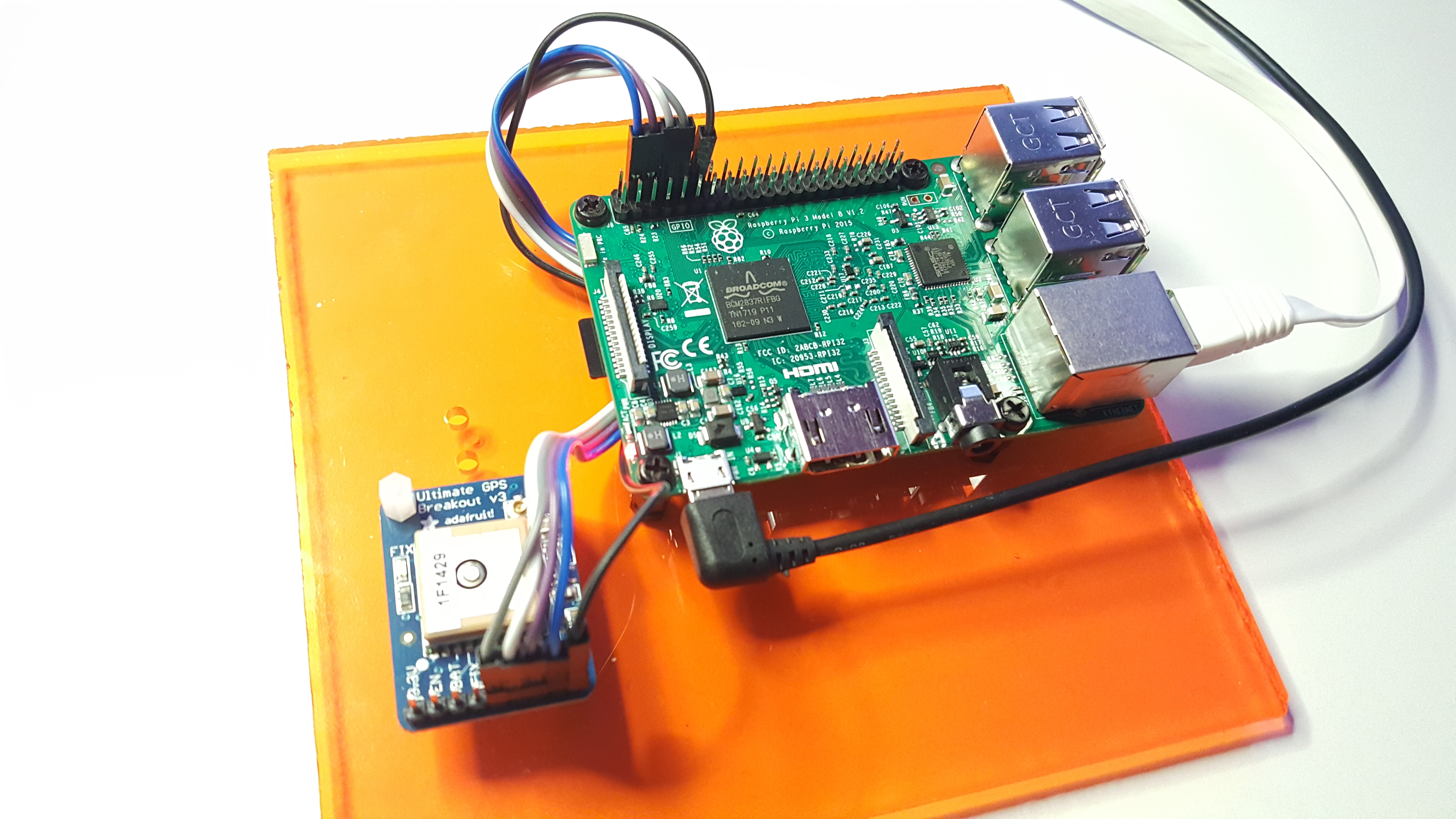
- Raspberry Pi B+ (on red Plexiglass): Has a GPIO board from Ciseco called the Slice of Pi that supports an xbee coordinator configured radio. It is running Raspbian OS and a python script that collects the serial data being collected by the XBee radio. The metric data is collected, bundled up and formatted, and sent to a Node-Red TCP Socket module. It also has an application named mochad-0.1.16 that provides X-10 device connectivity.
- Beaglebone Black (on blue Plexiglass): Running Debian Wheezy and installed with Node-Red (requires Node.js; should already be installed on Wheezy)
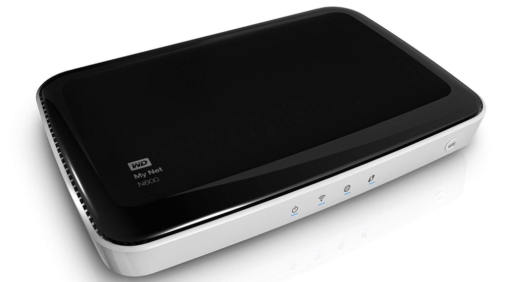
- Odroid C-1 (on orange Plexiglas): Running Ubuntu 14.04.2 LTS with Graphite and Grafana installed to provide a data store and data charting for all the sensor data.
When loading up an OS on these gateway devices, the basic process is to load an image file onto a MicroSD card that stands in as the computer’s bootable hard disk. I prefer using Win32 Disk Imager and I found ApplePi-Baker to be useful on Mac OS X. There’s a great overview of different methods here: http://elinux.org/RPi_Easy_SD_Card_Setup
Sensor Gateway
Download the OS image here. Read instructions here and learn about how to burn an OS image to a MicroSD card using WinDiskImager32. More info about setting up a MicroSD card here.
The Raspberry Pi sensor gateway has a GPIO PCB from Ciseco, the Slice of Pi, that supports an xbee radio. This XBee radio is configured to be the coordinator radio for all my XBee Sensor PCBs (described above). There is a python script, sensorgate2.py, that reads the data being received from the XBee radio via a serial port. Sample code on Github.
Using a software configuration tool from Digi (manufacturer of XBee radios) called X-CTU, and an XBee FTDI device (from AdaFruit, or Sparkfun – FTDI friend needed), you can set the configuration of the XBee modules. Here are the critical settings for my setup:
AP=2
CE=1
MY=1234
ID=1111 (same for all radios in your system)
CH=0C (same for all radios in your system)
To start the python script whenever the Raspi boots up, you’ll need an init script. Find a sample on Github.
Once you place this file in /etc/init.d, run this command:
# update-rc.d tinaja_sensor defaults
Once this is set up, the python script will start-up at boot-time, or you can manually start and stop the script when you make changes like this:
# service tinaja_sensor stop
# service tinaja_sensor start
Node-Red Gateway
This gateway was built using a BeagleBone Black, Revision B. It is running the OS, BeagleBoard.org BeagleBone Debian.
Download the OS image here. Read instructions here and learn about how to burn an OS image to a MicroSD card using WinDiskImager32. More info about setting up a MicroSD card here.
Download the OS image here. Read instructions here and learn about how to burn an OS image to a MicroSD card using WinDiskImager32. More info about setting up a MicroSD card here.
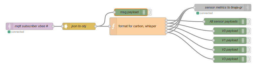
Node-Red is a web based application with a drag-and-drop user interface that makes it possible to build data flows by dragging various components on to the design surface (http web services, tcp socket listeners, MQTT, functional blocks, format converters, etc.) and connecting them with rubber-band connectors that direct the “flow” of data between components. 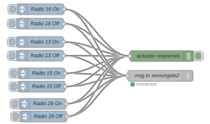
This gateway device is responsible for managing the connectivity and the logical flow between the sensors and actuators. All of the sensors in my home direct their metric data to a web service or a simple TCP Socket which are listening within Node-Red. From Node-Red, the data can be directed to various destinations such as a data store, a chart, an actuator such as a relay, a light switch, an alerting system, or even a controller for central heating and cooling. These definitions are called flows and are store on disk in JSON format.
Node-Red is built on Node.js (based on Javascript) and the BeagleBone Debian Image comes with that pre-installed. The best way to get Node-Red installed is to follow the instructions for BeagleBone Black on the Node-Red web site: http://nodered.org/docs/hardware/beagleboneblack.html
If you’d like to use a Raspberry Pi instead of BeagleBone Black you can look at a specialized distro called TheThingBox – http://thethingbox.io/. It is an OS image pre-loaded with Node-Red.
Node-Red Flows
A Node-Red flow is a definition of a collection of nodes modules which are strung together in Node-Red. You can read about flows on the Node-RED site here. and see a sampling of available nodes and flows on the Node-RED web site. You can find some of my flows on Github.
Charting and Analytics Server
This device is an Odroid C1 running Ubuntu 14.04. It’s basically a Raspberry Pi clone with a quad core CPU and 1G of RAM. It can run from a MicroSD as the other micro-computers or, it can run significantly faster ( and significantly more expensively) on an eMMC memory card. You can purchase these devices in the US from a company called Ameridroid.com.
I have utilized this server to host our data storage and to provide our charting and analysis services. For that I use Graphite, a python based Django web application which includes a TCP socket listener, named Carbon, for all the data input and a round robin database (RRD) known as Whisper. Graphite at its core is a capable charting application but it looks kind of dry. To see cool looking charts with an easy to design web interface I use Grafana.
Graphite
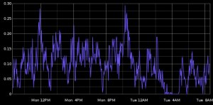
Graphite Chart Style
Grafana Chart Style
Graphite is a comprehensive application and it has a bunch of moving parts. The basic process of setting this up is to install Graphite the various supporting components:
- Carbon, the TCP Socket listener for all the data
- Whisper – the round robin database
- Graphite – the web application runs in Apache and has these prerequisites:
You can read the Graphite install instructions here.
Grafana
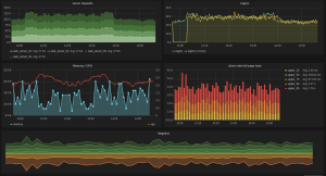
Grafana Chart Style
Next comes Grafana. It is a fork of a component that comes with an application known as ELK (Elasticsearch, Logstash. Kibana). I’ll let you figure out from which component it is derived.
When I originally installed Grafana it was with version 1.8 and it required the addition of Elasticsearch and Java. Version 2.x does not have the Elasticsearch/Java requirement so I would recommend 2.x. You can read about installing Grafana here. The simple approach requires 3 commands:
# wget https://grafanarel.s3.amazonaws.com/builds/grafana_2.1.2_amd64.deb
# sudo apt-get install adduser libfontconfig
# sudo dpkg -i grafana_2.1.2.deb
Wifi Controlled Light (LED)
This setup uses an ESP8266 wi-fi device as a web server which is waiting for a URL web service request that toggles an LED on/off. Of course the LED stands in for a relay or anything you’d like to switch on and off. You can find the code I used here.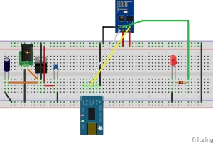
Here’s the Fritzing breadboard diagram.
What’s Next?
From here going forward, I’ve got some more projects to work on. One is to have all the system events logged and to have a voice system that announces the events; kitchen light on, garage door opened, and so on. It’s a precursor to a voice control system. I’d like to set up a wall switch replacement that contains environmental sensors (temp, humidity, light, presence) and capacitor touch switches for a simple control surface. I’d also like to manage conditioned air to each room in the house based on metrics received from the wall plate sensors in each room. In other words it would look like a dozen very inexpensive thermostats distributed all around the house and controlling the air conditioning on a room to room basis.
If you get here and find this article meaningful but find something I could improve upon, please let me know. Thanks.